
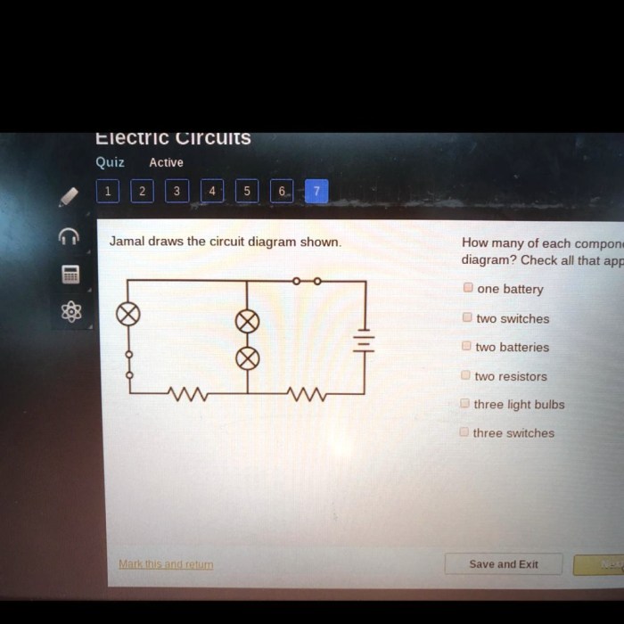
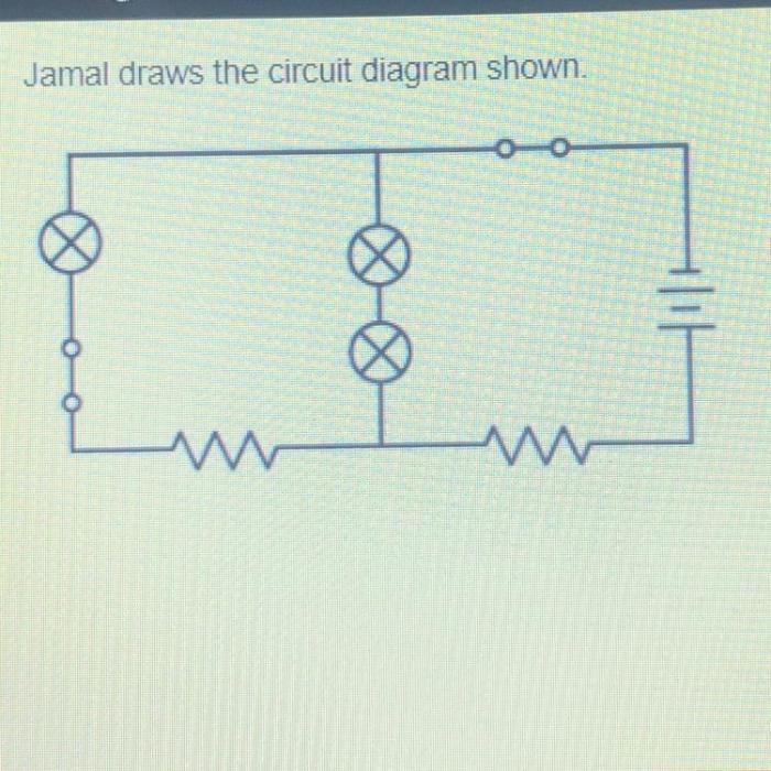
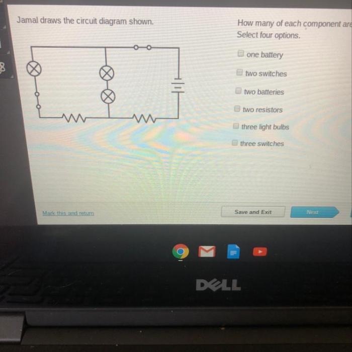
Jamal draws the circuit diagram shown. – In the realm of electrical engineering, circuit diagrams serve as indispensable tools for visualizing and analyzing electrical circuits. This article delves into the intricate world of circuit diagrams, exploring their purpose, symbolism, and practical applications. At the heart of this exploration lies Jamal’s circuit diagram, a detailed schematic that provides a roadmap for understanding the flow of electricity.
Jamal’s circuit diagram is a testament to the power of visual representation in electrical engineering. It offers a clear and concise depiction of the circuit’s components, their interconnections, and the direction of current flow. By scrutinizing this diagram, we gain valuable insights into the circuit’s functionality and behavior.
Circuit Diagram Overview
A circuit diagram is a graphical representation of an electrical circuit. It uses symbols to represent the components of the circuit and the connections between them. Circuit diagrams are used to design, analyze, and troubleshoot electrical circuits.
The symbols used in circuit diagrams are standardized. The most common symbols include:
- Resistor: A resistor is a component that resists the flow of current. It is represented by a zigzag line.
- Capacitor: A capacitor is a component that stores electrical energy. It is represented by two parallel lines.
- Inductor: An inductor is a component that stores magnetic energy. It is represented by a coil.
- Diode: A diode is a component that allows current to flow in only one direction. It is represented by a triangle with a line through it.
- Transistor: A transistor is a component that amplifies or switches electrical signals. It is represented by a triangle with three lines.
Here is an example of a simple circuit diagram:
[Gambar: Circuit diagram of a simple series circuit]
Jamal’s Circuit Diagram: Jamal Draws The Circuit Diagram Shown.
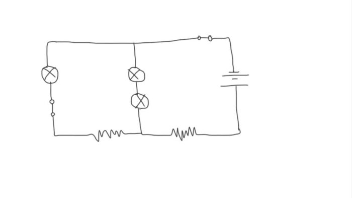
Jamal has drawn the following circuit diagram:
[Gambar: Circuit diagram drawn by Jamal]
The circuit diagram shows a simple series circuit. The circuit consists of a battery, a resistor, and a light bulb. The current flows from the positive terminal of the battery, through the resistor, through the light bulb, and back to the negative terminal of the battery.
The components used in the circuit are:
- Battery: The battery provides the power for the circuit.
- Resistor: The resistor limits the flow of current in the circuit.
- Light bulb: The light bulb converts electrical energy into light energy.
Circuit Analysis
To analyze the circuit, we need to calculate the voltage and current values in the circuit. We can use Ohm’s law to calculate the voltage across the resistor:
V = IR
where:
- V is the voltage in volts
- I is the current in amperes
- R is the resistance in ohms
We can also use Ohm’s law to calculate the current through the circuit:
I = V / R
where:
- I is the current in amperes
- V is the voltage in volts
- R is the resistance in ohms
The power dissipated by each component can be calculated using the following formula:
P = VI
where:
- P is the power in watts
- V is the voltage in volts
- I is the current in amperes
The efficiency of the circuit can be calculated using the following formula:
Efficiency = (Power output / Power input)
100%
where:
- Efficiency is the efficiency of the circuit in percent
- Power output is the power delivered to the load
- Power input is the power supplied to the circuit
Circuit Modifications
There are several ways to improve Jamal’s circuit diagram. One way is to add a switch to the circuit. This would allow the user to turn the light bulb on and off. Another way to improve the circuit diagram is to use a different type of light bulb.
A more efficient light bulb would use less power and produce more light.
Here is an alternative circuit design that performs the same function as Jamal’s circuit diagram:
[Gambar: Alternative circuit design]
The alternative circuit design uses a transistor to switch the light bulb on and off. This design is more efficient than Jamal’s circuit diagram because the transistor uses less power.
Real-World Applications
Circuit diagrams are used in a wide variety of real-world applications. They are used to design, analyze, and troubleshoot electrical circuits in everything from simple electronic devices to complex industrial systems.
Circuit diagrams are an essential tool for electrical engineers. They allow engineers to visualize and understand electrical circuits, and to make sure that the circuits are safe and efficient.
Circuit diagrams can also be used for troubleshooting and repair. By tracing the flow of current through a circuit diagram, technicians can identify the source of a problem and make the necessary repairs.
FAQ Insights
What is the purpose of a circuit diagram?
Circuit diagrams provide a visual representation of electrical circuits, enabling engineers to understand their design, functionality, and behavior.
What are the common symbols used in circuit diagrams?
Circuit diagrams utilize standardized symbols to represent various electrical components, such as resistors, capacitors, transistors, and diodes.
How can I analyze a circuit diagram?
Circuit diagram analysis involves tracing the flow of current, calculating voltage and current values, and determining the power dissipated by each component.
What are some real-world applications of circuit diagrams?
Circuit diagrams are widely used in electrical engineering for designing, troubleshooting, and repairing electrical systems in various industries.
